Self Calibrating Potentiometer

Update: Code edited for clarity and make sure you read pbrook’s comment

So I have a dial connected to an Arduino, a potentiometer (pot), it’s the typical item you might use for volume or brightness control, turning it all the way up to 11. Here’s the problem though, you’re reading in the analogue values of the potentiometer and you think it goes from 0 to 1023, possibly higher if it glitches a bit (though this is dependent on how it is handled in your code).

However, what you’re controlling, only goes from 0 to 10, maybe. What do you do?

Well one idea, is that you convert it to a percentage before making the comparison, I think this is effectively ‘normalising‘ the values – statistically speaking. This is really useful. So in this code I’m doing two things, one is that I am normalising the values but the other is that I am calibrating the values that I am reading.

Why should I be calibrating? Well, this code is then portable (the mathematics could apply to anything similar, as I see it), not only that but if the ‘pot’ needs replacing, then if it is placed in the ‘maximum’ value position for a while, then it’ll be accurate (well enough so).

#include "math.h"

int sensorPin = A0;
int maxVal = 0;
float sensorValue = 0.0f;
float percentile = 0.0f;
float temp = 0.0f;

void setup() {
 Serial.begin(9600);
}

void loop() {
 sensorValue = analogRead(sensorPin);
 percentile = (sensorValue / maxVal) * 100;
 temp = fmod(percentile,10.0);
 if (temp > 0.5)
 {
     percentile += 0.5;
 }
 if (percentile > 100.4)
 {
     maxVal++;
 }
 else
 {
     Serial.println((int)percentile);
 }
}

The code utilises the C++ Math library, and rounds the value from the pot up (I think, I should probably double check it) using the function ‘fmod‘. If the pot is set at the maximum it is capable of being at, it will increase the ‘maxVal’ variable to work out the correct 100% value to calculate with.

If anyone has feedback or corrections on this, please comment!

Posted in Arduino, Projects | Tagged , , , , , , | 13 Comments

DIY circuit boards, and what to do when it all goes wrong

So there are lots of ways to do electronic projects, and most have been used at the hackspace – Breadboards, Stripboard, Variboard; but I wanted to try my hand at PCB making, opening up opportunities to work with surface mount chips as well as looking much neater.

The first issue you run into when starting with PCB stuff is the layout of the board.  As an opensource fan, I wanted to use opensource applications, and this is an area that I found was problematic – KiCad is overly complex and expects a lot of prior knowledge, Eagle isn’t opensource (there’s a free version, with restrictions) and others are less established, crashy or require a lot of hoop-jumping to install.

I decided to go with Fritzing, which still has various issues, such as random crashing and a very “interesting” autorouter, and the fact that to get the latest, less-crashy version, you have to download the binary version from the website or compile your own (no ppa or packaged versions).

I found that the multi-step process of Fritzing (breadboard -> schematic -> pcb) was a great idea but some of the things I wanted were not breadboardy (isp header, 1mil sockets) and also the circuit I was building really benefits from a wide not long breadboard and those don’t exist in Fritzing. The main problem though is that when you finally lay out the PCB and connect what you want to connect, then hit the autoroute button, those it thinks are unroutable it disconnects.  Then you have to re-lay out the board and remember what connected to where. This lead me to a board with wrong routing that I manufactured.

Thankfully, all was not lost, we rescued the circuit, but I’m getting ahead of myself…  The method I used to make the board is a common one – print onto laser transparency, expose to UV (actually used a standard energy saver light), develop for about a minute and then etch in a tray of acid.

I then broke about 4 drill bits trying to use the pillar drill to drill the holes, finally resorting to a dremmel, which actually seems easier and about as accurate.

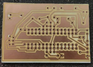
The "ShrimPCB" v1

The "ShrimPCB" v1

Okay, so some of the holes were not perfect but that was to be expected.  I went ahead and soldered the board up and then was quite confused when it didn’t work.  With the help of one of the other hackers we located the causes – three routing errors in total, and some tracks were too close together, causing shorts.

Using a craft knife to cut tracks, using tracks that were aimed to be for the reset button (who needs that?!) and jump wires, we were pretty sure that the circuit was correct. Unfortunately, the board still didn’t work.

We scratched our heads a bit, followed the traces with a multimeter and then it struck what the problem was – the copper was on the wrong side of the board.  Effectively, the transparency was the wrong way round when the board was exposed, leading to a reversed chip layout.

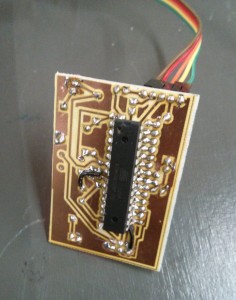
Almost ready to throw the board away, we decided that the time spent on making the board would be well worth the two minutes to “deadbug” the circuit – effectively treat the dip chip as a surface-mount chip and solder it to the copper side.

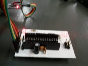
The finished board looks fine if somewhat blurry here (apart from the fudged pins from inaccurate drilling and how is that arduino clone running blink without a chip?!) from the top :-

Top view, blurry, better pic will be uploaded later

Top view, blurry, better pic will be uploaded later

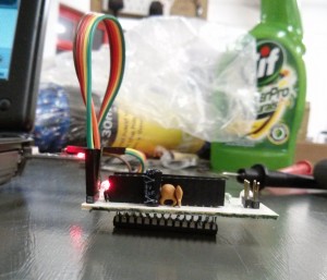
Side on and from underneath though makes people squirm and draw back in horror!

Side View, showing board resting on chip

Side View, showing board resting on chipBottom view, showing the mess it actually is

Bottom view, showing the mess it actually is

Bottom view, showing the mess it actually is

So version 2 will be so much better!

P.S. The reason for the word “ShrimPCB” is that I’m using the fantastic “Shrimp” project’s circuit as a base for this Arduino clone, once I have made a working version that doesn’t require the fixes as above, the fritzing and svg files will be on github and/or thingiverse.

Posted in Uncategorized | 1 Comment

3rd Leeds Raspberry Jam – 16th February

Angus explains the workings of his Minecraft to PiFace hack.

We’ll be hosting the 3rd Leeds Raspberry Jam on the 16th Feb starting 12pm. Previous events have seen mini arcade systems, Raspberry Pi ports of classic games, and the amazing PiFace to Minecraft hack from Angus (As featured on Hack a Day!)

Posted in Uncategorized | Leave a comment

For those forgetful members

Edge Lit Acrylic Sign

If you forget where you are you can just check our new sign (yes, blue LEDs are a bit over-used, but it’s the Leeds Hackspace colour, so I couldn’t resist).

The sign is laser cut from 3mm transparent acrylic with a nice deep etch of the name and logo. The top edge of the acrylic has cutouts for a row of high brightness LEDs (U shaped holes that the LEDs fit snugly into in order to capture the maximum amount of their light output). The end result is rather nice. Now it just needs wiring to automatically turn on when the hackspace is occupied.

Posted in Uncategorized | Leave a comment

MendelMax Upgrade

MendelMax Shaft Couplers

Our MendelMax 3D printer hasn’t even printed anything yet (The first extruder we fitted was unfortunately far from serviceable, and we’re still awaiting some parts for the replacement – a tried and tested design) but we’ve upgrading parts on it already. The printed shaft couplers never seemed particularly robust, and since we’ve got our lathe working it seemed like an excuse to produce something useful. I’m rather pleased with the result, they should be far more rigid than the printed parts they replace, and they’ll fit in rather nicely with the black and aluminium colour scheme.

Posted in 3D Printers, Projects | 1 Comment

Weaponry makes the Perfect Gift

As a member of the Hackspace it crosses a few members minds of how to use the functionality of the space with the opportunity of giving a present to someone.

A long friend of mine is a devout fanatic of the TMNT – collecting nigh everything available and it’s his 30th birthday this year near christmas. So myself and the girlfriend thought, what better than to give him something he cannot buy?

With Jo‘s talents in Fimo and the resources available to me, we decided upon figurines. However, these required weapons. With a bit of resourcefulness, soldering, patience and heavy hitting by myself and pbrook and some laser off-cuts we managed to produce something resembling the TMNT load-out:

TMNT Weapons

They have since been touched up with a bit of paint to cover the initial attempts at soldering the metal pieces together and neaten up the blades from being hammered. The ‘grips’ on the swords may be lightly painted, to retain the look formed by squishing the metal under great pressure by a vice.

I’m quite happy with the result and the ‘chain’ for the nun-chucks, made by braiding wire together.

Update: Here are the finished items:

TMNT Weapons

Posted in Models | Tagged , , , , | 2 Comments

Is it me, or is it hot in here?

As anyone who’s been to the hackspace recently will know, it’s often not the warmest place.  This has led to some members becoming a bit obsessed with temperature sensors.  Our resident bot already has a temperature sensor, but we had our suspicions about its accuracy, and it doesn’t have a convenient readout.

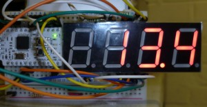
Minimus based temperature sensor

I recently acquired a nice 1″x4digit 7-segment LED displays. Unfortunately these came without datasheet, so the first task was to reverse-engineer the pinout.  It turns out they aren’t 5v tolerant.  Applying 5v causes the segment to briefly glow orange, followed by the release of magic smoke. After installing some limiting resistors I figured out the wiring for the remaining 3.5 digits!

This combined with a minimus (small arduino-like microcontroller) and a DS18B20 temperature sensor gives in a handy self-contained temperature readout.  About the only notable oddness is I chose to multiplex round the segments rather than across the digits.

This all seemed a bit too easy.  We’ve recently had a big pile of discrete logic chips donated (mostly 74 series).  A digital temperature sensor seemed like a reasonable project to make use of them.  i.e. replicate the device above without using a micro-controller.

The design is constructed as follows:

  • A thermistor in voltage divider, driving the analog input of an ADC0804.
  • An 8-bit (dual 4-bit ripple connected 74LS191) binary count-down counter.  Load with the ADC output value.  Clock gated on zero detect.
  • Dual 4-bit BCD counter (CD4518 in ripple configuration).  Counts up from zero synchronously with the count-down counter.
  • Dual 4-bit tri-state buffer (74LS244) multiplexing BCD counter output onto BCD 7-segment driver (CD4511).
  • Common cathode 4-digit (2 used) 7-segment display with N-channel MOSFET (BS170) drivers on the cathodes.
  • Control logic consisting of 2-bit counter (74LS191, bit 2->reset) feeding 2-to-4 address decoder (74F138).  The 4 outputs trigger the ADC conversion, counter reload, and two display digits in turn.
  • 30KHz 555 based oscillator clock input to ADC and counters.
  • 200Hz  555 oscillator clock input to control logic.
  • Misc NOT (4069) and AND (7400) gates.

A few issues encountered along the way:

  • It’s worth trimming the legs on capacitors and resistors before plugging them into breadboard.  Otherwise adjacent long-legged components are liable to short together causing intermittent hard to debug failures.
  • The oscillators are quite noisy.  It’s important to have sufficient power supply decoupling/smoothing capacitors, especially on long supply rails.
  • I initially got the clock polarity wrong for the count-up timer.  This resulted in a race between the active clock edge and the reset/enable signals.  Inverting the clock signal gave a stable count.
  • My nice jumper wires are slightly more than 0.1″ diameter.  i.e. they don’t quite fit in adjacent breadboard sockets. After a while I ended up just using lengths of solid core equipment wire.
  • Logic analyzers are really handy.  I don’t have one but bodged together a cheap one using a Minimus/Arduino. It’s not fancy, but more than sufficient for debugging 30KHz signals.

There are two multi-turn potentiometers for adjustment.  The first sets the zero point via the ADC negative input.  The second forms the potential divider with the thermistor, and allows the scale to be adjusted.  While the temperature response is nonlinear, within a small range (say 0-30°C) it’s not too far off.

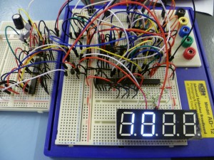
The finished build spans two and a half large (~1200 hole) breadboards, and runs off a 5v supply.  It displays positive temperatures to within about a degree.

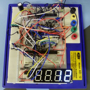
Update: A bit of rewiring and it now fits on a single (large) board.

Discrete logic implementation


"Compact" discrete logic layout

Posted in Projects | 2 Comments

Leeds Raspberry Jam – 15th December

We’re hosting Leeds’ first Raspberry Jam!  For anyone who’s interested in the Raspberry Pi and would like to meet up with other people who share that interest.  There’s no strict structure to the meetup, but we plan to have demonstrations of things people have done with their Pi, maybe a talk or two on people’s projects, and hopefully plenty of people on hand to help out with any issues people are having.

You don’t have to have a Raspberry Pi to come along!  In fact, this might be a good opportunity to see what all the fuss is about.

If you’re interested in attending then please register here so we have some idea of numbers attending.

Posted in Events, LHS Events | Leave a comment

Workshop Update

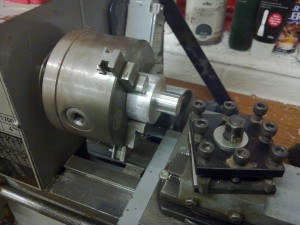
First job in the lathe

I’m happy to report that our lathe is now working. There’s a shortage of tooling at the moment, but hopefully this situation will improve over the next few weeks. Details on the lathe are being collected in our wiki.

Posted in Uncategorized | Leave a comment

Come Find Us – November 2012

From the 23rd to the 25th of November creative places around Mabgate and Sheepscar will be open to the public and we’re happy to announce we’ll be taking part. The hackspace will be open from 12pm to 6pm on Saturday the 24th and Sunday the 25th of November for you to drop in and investigate the projects we’re working on and the facilities we have available.

Further details of Come Find Us events can be found here.

Posted in Uncategorized | Leave a comment