
Introduction
The 6040 laser cutter in Leeds Hackspace has never been fully serviced.
Various types of laser cutter can be sourced from china and its always a mixed bag of what kind of components you get making up yours. The 6040 in LHS is no different, its received incremental updates but recently strange problems have infrequently occurred and band-aid fixes have been applied (both hardware and software based!)
A full TLC service for the laser was long overdue, so the service has now begun!
As specified in the google groups post, several phases were identified.
Wot is our lasor
Our laser is an older type, identifiable by its belt drive system combined with a cylindrical linear bearing on one side and wheels. Newer lasers come with linear block bearings on one or all sides driven by screw or split belts. Our drive system is usually seen in the “mini” type K40 / 40W machines, with the others in larger more powerful units, sometimes with reduced stepper gears.
First things first
I identified the X and Y stepper motors incase they need replacing.
Y axis is a dual shaft 17HW441ON-03AD02 with standard 4 wire cable; driving a coupled shaft one end with belt gears.
X axis is a single shaft 17HW3448N-15AD with a short 4 wire cable that breaks out onto the ribbon that also carries the end stop sensors from the electronics. This stepper rides on the Y axis linear bearing – again it has the belt gear attached to its shaft. – A potential improvement here would be to use standard cabling (Amp draw over ribbon?) and/or to install mechanical end stops like this that would increase work area.
Remove the gantry frame
The gantry frame was held into the base of the laser by 4 bolts, interestingly the frame rests over the holes where the Z axis shaft bearings are; they are not level so the frame essentially is clamped down ontop of these moving shafts and never fully meets with the laser casing. – An improvement here could be to washer the frame so it has 4 proper points of contact.
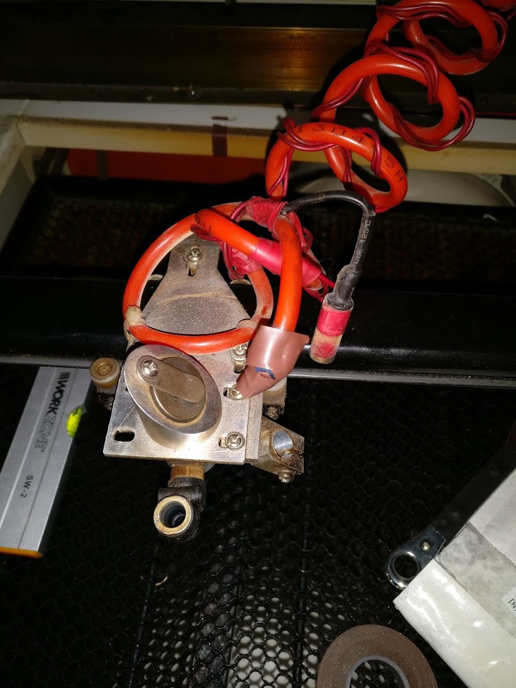
To remove the frame required the disconnection of the ribbon cable to the X axis and the stepper cable to the Y, as well as the air assist and laser dot power connected to the gantry itself via zip ties.
The gantry frame is now loose and can be teased out in a specific geometric arrangement to get a square peg out of a square hole!
With the gantry frame removed we can check its construction; its made from special sections of what looks like zinc coated steel that are jointed with mechanical screws. Overall a surprisingly nice frame, lacking horrible welds and scoring points for serviceability.
The frame was checked to be square (it is!) so that rules out one of the major mechanical problems that could have been possible and have been seen elsewhere… frame buckling!
Belts and bearings!
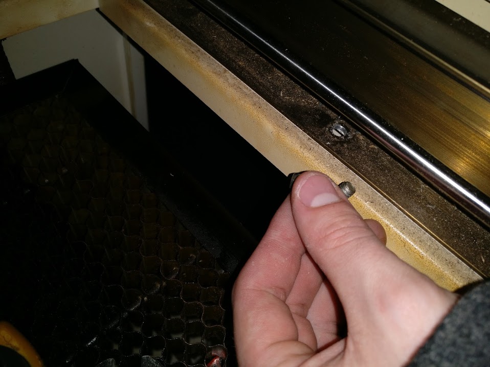
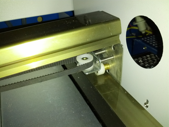
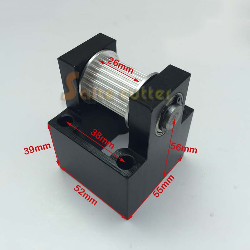
The belt pulleys and gears look to be worn, the tensions were very wrong and the linear bearing is very “bitey”. The tension systems are very simple, but prone to wear and not the same as the ones in the newer split belt systems, they are not a great design as they rely on the pulley as both a bearing and for tension / stability. To give this context, our laser has a pully shaft of 2mm, held in tension with a single set screw: comparison below with a nice big block with ring’ed bearings each side seen on better machines.
The Y axis non linear bearing end runs on a single wheel that is free in the frame channel, no secondary bearing here! However after a small cleanup and fine-tune the gantry was moving much more nicely, without bite: its very vital that the X axis belts are balanced closely.
A better bit of news is that the X axis power shaft is well supported by decent sealed bearings on both ends.
It would also seem that the Y axis belt clamp on the gantry head is attached on the wrong side, leading to a large angle at the extremes of motion where the head approaches a gear or pully.
The future
A full clean up and reconstruction of the gantry head, along with the gantry wheels should help get everything running smoothly again, hopefully ruling out mechanical issues for the LHS laser!
Nice work!