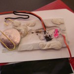
This year I decided to have a go at building my own electronic christmas card. As I have no real artistic skill, I did cheat a little, and started with a regular off the shelf card, featuring a snowman on a raised mount. My plan was to make the snowman light up.
Sticking an LED on the front of a card is hardly a new idea. With some of the conductive inks you can even do it without and actual wires or soldering! However there is one problem: Power consumption. While LEDs don’t use a huge amount of power power (a few mA), I want this device to remain operational for several days off a single coin cell. These only have enough juice to power an LED for a day or two at most.
I had a spare attiny25 left over from a previous project, so I though I’d see if I could use that to add smarts. If I only turn the LED on for a few seconds every minute, the battery should be good for at least a week. Once I have a microcontroller in there, I can also add more complicated behavior: fading/glowing LEDs and a capacative touch sensor to make it perform on demand.
Initial tests were not promising. A gowing LED (using the attiny PWM output) triggered by a capacative touch sensor (10Mohm resistor and a sheet of tinfoil) consumed over 5mA, not including the LED itself (annother 2mA). I know the atmega chips are capable of extremely low power consumption, so clearly my software needded some improvement.
First the core was running at 8MHz. I really don’t need all that processing power, so turn that right down. In fact the 128KHz watchdog oscillator is good enough for my needs. Using that also means I don’t need to power up the high frequency OSC at all. This gets me down to about 300uA (0.3mA). Not a bad start, but I’m pretty sure I can do better.
I’m only using a single PWM channel (Timer0). Turning off unused peripherals (Timer1, ADC, USI) saves annother 50uA.
As I’m using the hardware PWM output, my code isn’t actually doing anything most of the time. The Timer hardware does all the heavy lifting for generating the PWM signal, and adjusting the brightness is done in response to the timer overflow interrupt. The rest of the time It’s just sitting around waiting for something to happen.
Putting the core into idle mode brings power consumption down to about 65uA (plus the LED). This is as good as we can do when the LED is on.
But the LED is off ~90% of the time. All I need to do is check the touch sensor periodically. I can put the chip into deep sleep power down mode, using the watchdog to wake up a couple of times a second to check the touch sensor. Doing this gets average power consumption of 5uA while the LED is off. Or put annother way, low enough to last well over a year (assuming we never actually turn the LED on).
All that’s left now is to solder everything together, bore out the eye sockets to fit 3mm LEDs, and and mount it inside the card. The end result is a little creepy, but I’m pretty pleased overall.