
I’ve recently been reviving a Thecus N2100 NAS box. This is a low-power ARM machine with 512Mb ram, 4 USB ports, a pair of 3.5″ SATA drive bays and lots of potential for hacking. However it does have one major flaw:
It requires manual intervention to turn on. When you apply power, noting happens. To bring the thing to life you have to then press the soft power button on the front. This is complete insanity for a machine that you want to hide in a dark corner and never physically interact with again. Whoever designed it should be ashamed of themselves.
Simply wedging the power button permanently on causes a continuous power-on/reboot cycle, so we need something a bit smarter. Experimentation showed that holding the button while applying power, then releasing shortly afterward does the trick. This sounds like a job for a 555 monostable and a relay.
I’ve never actually used a 555 before, so the first step is to see whether a power-on monostable actually works as expected. With a bit of cribbing off the internet I decided I want to tie the trigger and threshold inputs to the middle of an R-C bridge, !reset pulled high, discharge not connected and output does what it says on the tin. R=1M ,C=2uF should give me a 2 second delay, long enough to avoid issues when I fumble the power plug. 12v is within the operating range of a 555, and timing isn’t critical, so need to mess with additional regulators or trim pots. My relay isn’t breadboard friendly, so an excessively large LED was used on the breadboard mockup. Amazingly it worked first time! The LED illuminates when power is applied, and goes off after a coupe of seconds.
The next step was to build on strip board with the relay. I started by laying it out on paper, but realized half way through assembly that I’d omitted the protection diodes. Fortunately this was before I’d soldered anything in place. At this point I abandoned the paper layout, and rearranged components on the board until everything fit. I’m really pleased with the end result, even managing to pull all the connections to a single header block. Testing showed that the circuit still works. Some initial concern because the relay is so tiny I couldn’t hear it clicking, but probing with a multimeter showed it working as expected.
The final step is to install in the NAS. Flying leads from the underside of the motherboard connect the power jack and switch to the new board via one of my nifty crimp-your-own connectors. A blob of hot glue holds the whole thing in place.
The box has now been cured of its need for human contact, and can be safely left in the bottom of the rack with all the other grown-up hardware.
All I need to do now is graft on a serial port and figure out why the new kernel fails to boot…
-
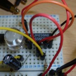
- Flashes exactly once!
-
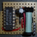
- Soldered and ready to go
-
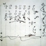
- It makes sense to me. And it’s wrong.
-
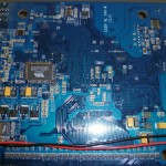
- Hooking into the motherboard
-
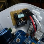
- Button pressing widget installed and connected
Hey Paul,
Assuming that the power switch just goes into a logic input, it’s quite possible that a simple RC circuit could have generated the required pulse. Or was it more complicated than that?
It effectively is an RC circuit. The 555 is acting as a comparator, with the relay providing electrical isolation (the power switch will almost certainly be driving low voltage data pin). Probably overkill, but will work reliably in all circumstances.
In theory a capacitor accross the reset switch should have a similar effect (forming an RC circuit with the pull up/down resistor). Both the input trigger threshold and pull-up resistor size are unknown, so trial end error is needed to find a suitable capacitor value. Pullups are typically 10k (c.f. the 1M in my circuit), with a substantially lower threshold, so you’re probably looking at a fairly chunky electrolytic capacitor. Yyou also need to empirically determine the correct polarity. For added fun the contents of that cap will be [near-]instantaneously discharged through the button when pressed, which the cheap microswitch probably isn’t rated for :-)