*UPDATE*: Code available at https://github.com/pbrook/owled
A couple of months ago we acquired an arcade cabinet from the lovely people at HacMan (it was non-working and surplus to requirements). Since then Martyn has been working on replacing the screen with a flat panel, upgrading the buttons and generally trying to make it a useful addition to our hackspace.
The most recent change was the addition of backlighting to the buttons.
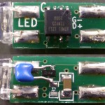
The buttons themselves use standard microswitches but have 2 extra spade terminals for backlighting – either by bulb or LED. The problem is how to drive an RGB LED over only 2 connections. The solution devised by Paul is to fit an ATTiny into the space for the bulb. It’s powered through its data pins and communication is via pulses on this power supply, allowing PWM control of the RGB elements of the LED to give full colour and brightness control.
The LEDs are controlled by a Minimus 32 which also acts as a joystick interface to the PC in the arcade cabinet allowing easy configuration of the joysticks and buttons within MAME.
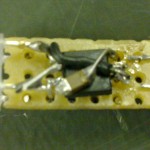
The first build is ugly, but functional.
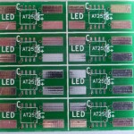
Once this was proven to work a proper PCB layout was developed and a batch of LEDs have been built for all the buttons in our machine.
Here’s the end result (Once their addresses are set each LED will be individually addressable, allowing the buttons to be lit as indicators for the game in play):
RGB Arcade Buttons from Jon Stockill on Vimeo.


This is an awesome idea! I have thought about doing it for replacement bulbs in my car.
I have had a look at the code, but don’t quite understand how the pulses are sent over the power line, and how the micro detects these.
Is the power line switched on and off, or is the voltage just modulated? What prevents the micro from switching off?
Cool!
Really interested in how you managed your cons over the power. Are you releasing schematics?
Please post the schematic in jpg or pdf format.
Thank you